
Engineering Drawing Basics Explained
An engineering drawing is a subcategory of technical drawings. The purpose is to convey all the information necessary for manufacturing a product or a part.To get more news about engineering drawing symbols and meanings, you can visit runsom.com official website.
Engineering drawings use standardised language and symbols. This makes understanding the drawings simple with little to no personal interpretation possibilities.
The Purpose of Engineering Drawings
As already said, such a technical drawing has all the information for manufacturing a part or welding and building an assembly. The info includes dimensions, part names and numbers, etc. So once a manufacturing engineer gets the drawing, he can start the production process without a second thought.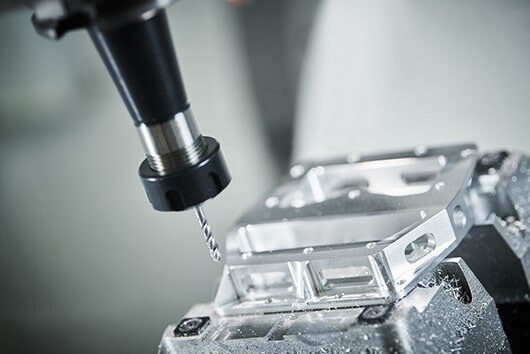
First, we have to pause for a second and address our own customers here to avoid confusion. The drawings you submit for instant pricing and manufacturing in our system do not need any of this. The same applies to 3D models. CAD files and drawings made according to our design tips include all the necessary information for making your product. The only time we ask for a drawing is if you want to specify tolerances.
How to Make Drawings?
A few decades ago, you would have had to sit down at a drawing board covered with papers of different size, rulers, callipers, etc. Today, all these instruments are still good for manual drafting but no contemporary manufacturer really wants such drawings.
Why? Because most of the machinery uses CNC systems that can read the information straight from the files and produce a cutting program accordingly. Drawings done by hand would just add a lot of manual work for manufacturing engineers.
So, we are left with only one option really – every engineer should use CAD (computer aided design) software because of its many advantages.
You can, of course, use CAD for making drawings from scratch. But the easier option is to first make a 3D model and create the drawings from that, as the programs generate the views with only a few clicks. All you need to do is add the dimensions. Having models also makes updating the drawings for revisions simple.
Types of Views
So let’s take a closer look at the different types of views that are often present in a manufacturing drawing. Each serves a certain purpose. Bear in mind that adding views should follow the same logic as dimensioning – include as little as possible and as much as necessary.
Isometric drawings show parts as three-dimensional. All the vertical lines stay vertical (compared to the front view) and otherwise parallel lines are shown at a 30-degree angle.
The lines that are vertical and parallel are in their true length. This means you can use a ruler and the scaling of the drawing to easily measure the length straight from a paper drawing, for example. The same does not apply to angled lines.
It is important to distinguish the isometric view from a perspective view. A perspective view is an artistic one that represents an object as it seems to the eye. Engineers stay true to the dimensions rather than optical illusions.
This is the bread and butter of an engineering drawing. An orthographic view or orthographic projection is a way of representing a 3D object in 2 dimensions.
Thus, a 2D view has to convey everything necessary for part production. This kind of representation allows avoiding any kind of distortion of lengths.